| Name |
Description |
Instruments/Softwares |
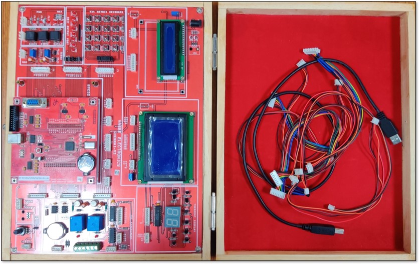
| Master ARM LPC2148 Development Board |
The base board of LPC2148 having different features. Some of the key highlights are- It has built in 2 no’s of 16 pin FRC connector for mother board accommodation, built in 2x16 line/4x20
line LCD display, built in 64X128 graphic display, built in 2 digit seven segment display, built in 2 relays with 3 Pin Molex connector, built in DS1307 RTC with Backup battery, built in variable pot for
ADC input, Built in 3 pin RMC for temperature sensor. built in 4X4 matrix key board built in 8 LEDs for LED blink experiment built in 3 Push to ON switches, built in 11 no’s of 8 Pin RMC connectors and 9 no’s
of 4 Pin RMC connectors for inter connection between mother board and base board. The mother board having built in n LPC2148 32 Bit Microcontroller, built in 2 nos. of 16 pin FRC Connector to insert in the Base
board slot, built in USB for ISP Programming, built in 20 pin FRC for JTAG interface, built in 9 pin D Type connector for RS232 Interface, USB Powered with built in 3.3v regulators and built in Battery packup for
Onchip RTC.
|
 |
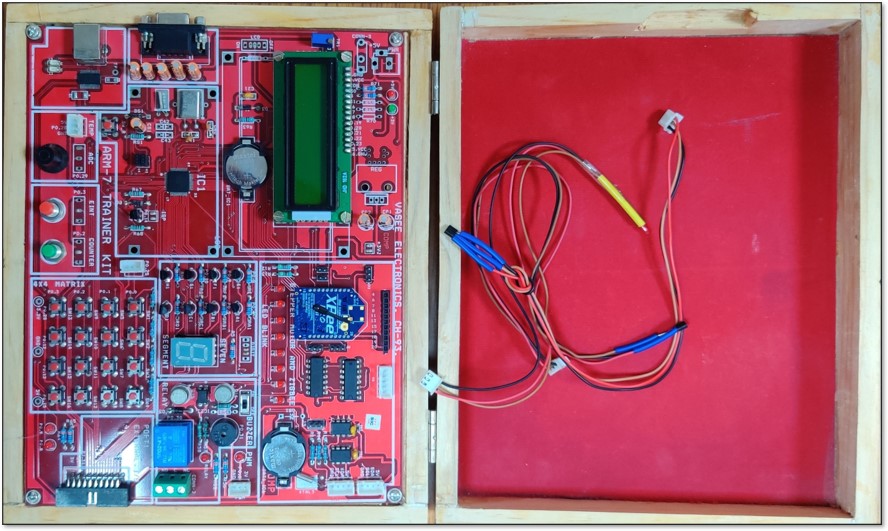
| Mini ARM LPC2148 Development Board |
The key features of this development board are having built-in 16/32 bit TDMI-S Microcontroller, built-in 2x16 Line / 4x20 Line LCD Display, built-in ONE XBEE Wireless Module, built in 12 pin RMC
for wireless ADC/Digital port line, built in Stepper Motor Driver Circuit, built in 5 pin RMC for interfacing Stepper Motor, built in 8 leds for led blink experiment, etc. built-in 4 pin RMC for I2C0 port,
built-in 4 pin RMC for I2C1 port, built-in DS1307 RTC with Battery backup RAM, built-in I2C EEPROM(AT24C32), built-in 3 pin RMC for one PWM port line, built-in LED to indicate PWM output, built-in BUZZER with
ON/OFF Switch, built-in Relay with 3 pin Phoenix Connector, built-in 20 pin FRC for Port1 Output, built-in two LED for LED Blink Experiment, built-in 4x4 Matrix Keypad with single digit seven segment Display,
built-in Push to ON switch to trigger External Interrupt, built-in Push to ON switch for updating 32 bit Counter, built-in Pot for variable ADC input, built-in 3 pin RMC for 10 bit DAC Analog output, Built-in USB
for ISP program loading, built-in 9 pin ‘D’ type Connector for UART1 output, built-in 3pin RMC for Temperature Sensor LM35, built-in 3.0 V Battery for Internal RTC, Trainer Kit powered by USB, built-in 5V Power
Supply provided and built-in two LED for 5V & 3.3V indicator
|
 |
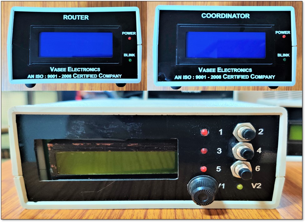
| Zigbee wireless network system |
This system consists of one coordinator and 3 routers each coordinator and three routers are having built in 2x16 line LCD and push to on switches and 3 LED’s. Each one can freely communicate with each other.
These are forming mesh network. The key features of the system are- built in LPC2148 32-bit microcontroller, CPU speed 60 MHz, on chip 512 kb flash, on chip 32 kb flash, on chip RTC, on chip two UARTs, built in
Xbee S2b connected with UART1, built in USB for ISP programming.
|
 |
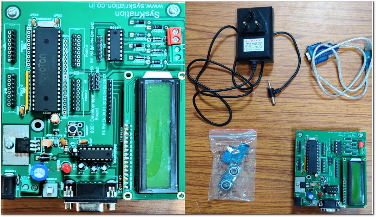
| 8051 Development Board with Accessories |
The 8051-development board has an inbuilt Nuvoton controller (W78E052). The Nuvoton W78E052D is an 8051-based CMOS microcontroller with 6-clock High-Speed Core, 20 MHz at 6 clks/cycle,
40 MHz at 12 clks/cycle, 8K Bytes ISP Flash, 256 Bytes RAM, Up to 36 I/O pins, Interrupt system with 8 sources and 4 priority levels, 3 16-bit timer/counters, 1 Watchdog timer, 1 full-duplex UART,
1 Power-Management Unit, and 2KBytes LDROM (Bootloader). The development board also supports 16x2 LCD interfacing, L293D DC motor driver interfacing and UART interfacing.
|
 |
