
MEMS AND NEMS COMPETENCY R&D LABORATORY
Proprietary software by: COMSOL Multiphysics
| Name | Description | Instruments/Softwares |
|---|---|---|
| Introduction | COMSOL Multiphysics® is a general-purpose simulation software for modeling designs, devices, and processes in all fields of engineering, manufacturing, and scientific research. In addition to using multiphysics modeling for your own projects, you can also turn your models into simulation applications and digital twins for use by other design teams, manufacturing departments, test labs, customers, and more. The platform product can be used on its own or expanded with functionality from any combination of add-on modules for simulating electromagnetics, structural mechanics, acoustics, fluid flow, heat transfer, and chemical engineering. The add-on modules and LiveLink™ products connect seamlessly for a modeling workflow that remains the same regardless of what you are modeling. |  |
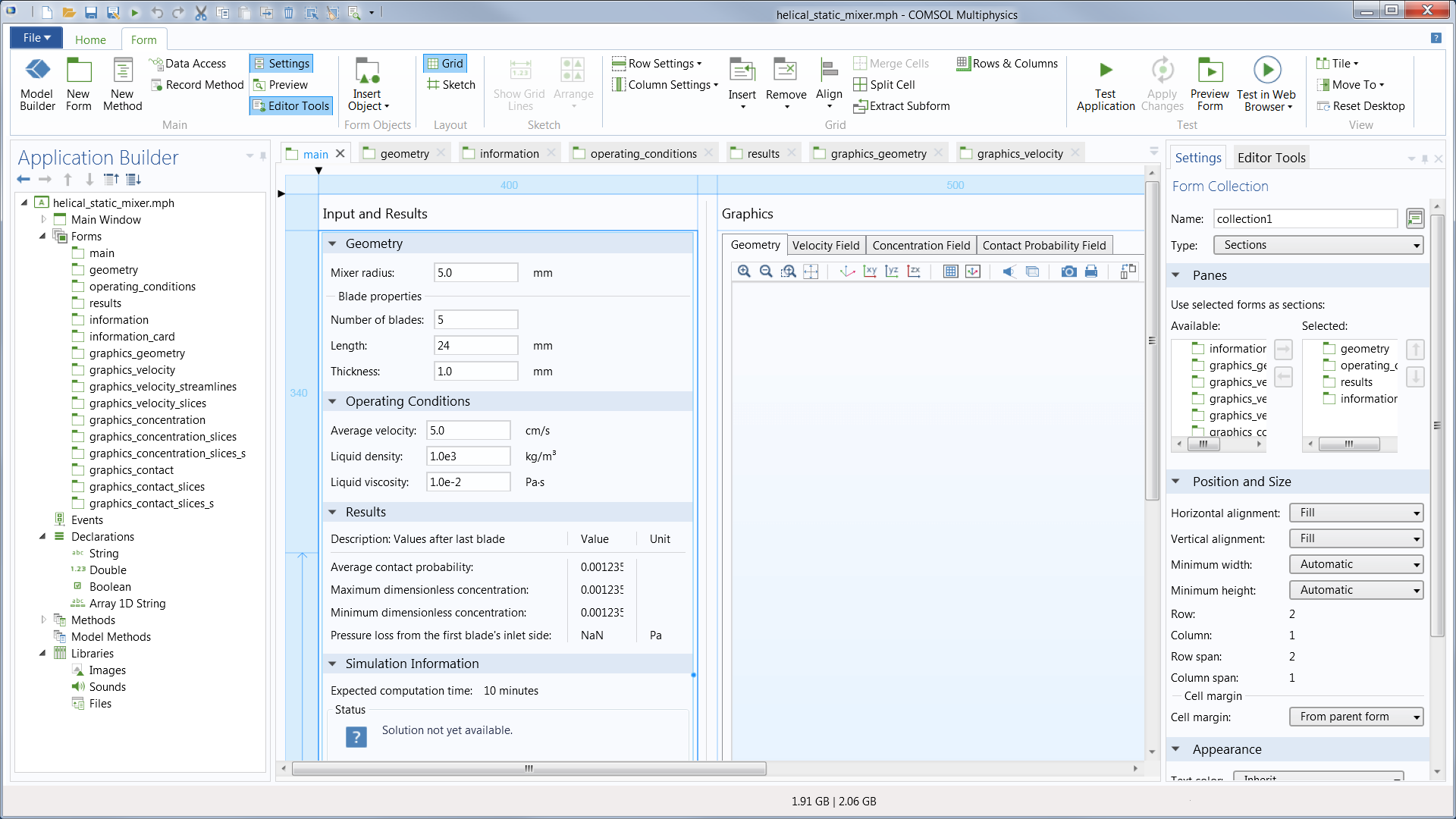
| Optimizing and Verifying Real-World Devices and Processes with Simulation | Engineers and scientists use the COMSOL Multiphysics® software to simulate designs, devices, and processes in all fields of engineering, manufacturing, and scientific research. COMSOL Multiphysics® is a simulation platform that encompasses all of the steps in the modeling workflow — from defining geometries, material properties, and the physics that describe specific phenomena to solving and postprocessing models for producing accurate and trustworthy results. To create models for use in specialized application areas or engineering fields, you can augment COMSOL Multiphysics® with any combination of add-on modules from the product suite. The interfacing products make it possible to also integrate simulation with other engineering and mathematical software used in product and process design. When you have developed a model, you can even convert it into a simulation application with a dedicated user interface, which can be designed for a very specific use by people beyond the R&D department. | 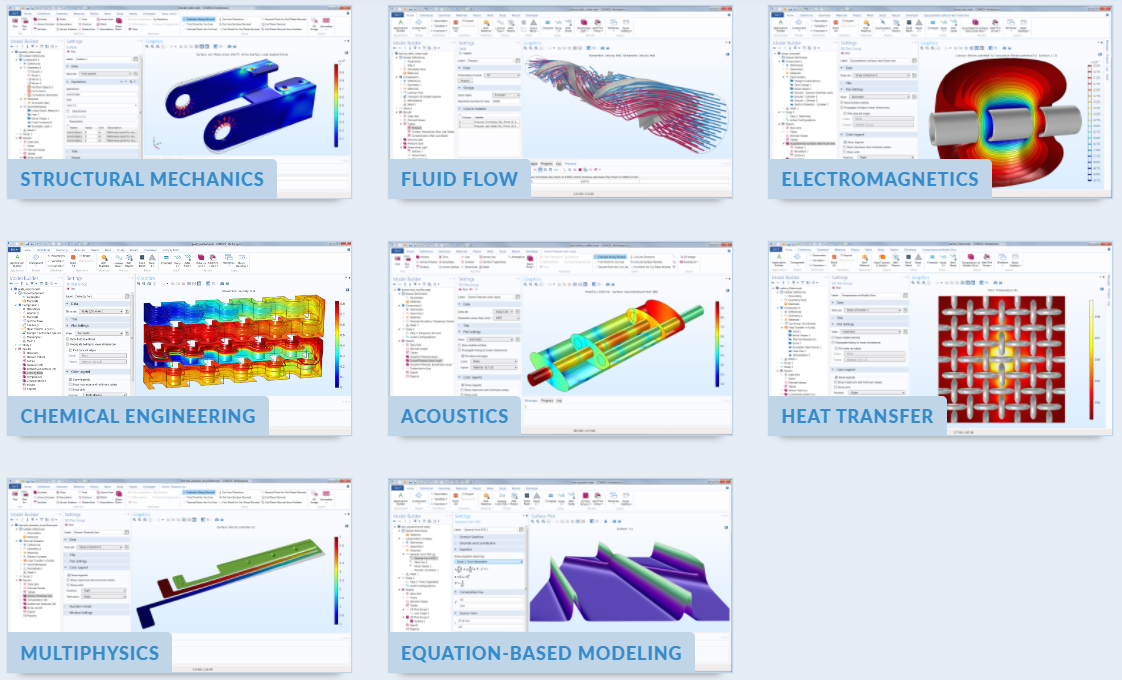 |
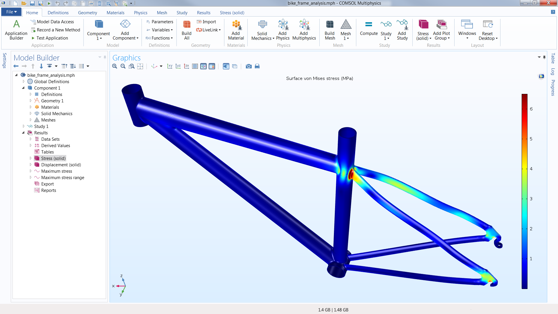
| Multiphysics Modeling Provides Accurate Results | Often, the key to successful engineering simulations is developing experimentally validated models that replace the use of experiments and prototypes alone, and give a deeper understanding of the studied design or process. Compared to running experimental methods or testing prototypes, modeling allows for quicker and often more efficient and accurate optimization of processes and devices. As a user of COMSOL Multiphysics®, you are free from the restrictive nature generally associated with simulation software and have complete control over all aspects of your model. You can also be creative in a way that is impossible or a lot harder with traditional approaches, thanks to the ability to couple any number of physics phenomena together and input user-defined physics descriptions, with associated equations and expressions, directly in the graphical user interface (GUI). Accurate multiphysics models consider a wide range of possible operating conditions and physical effects. This makes it possible to use models for understanding, designing, and optimizing processes and devices for realistic operating conditions. | 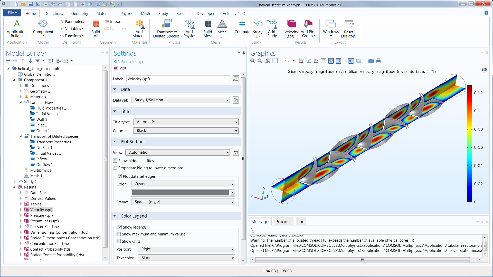 |
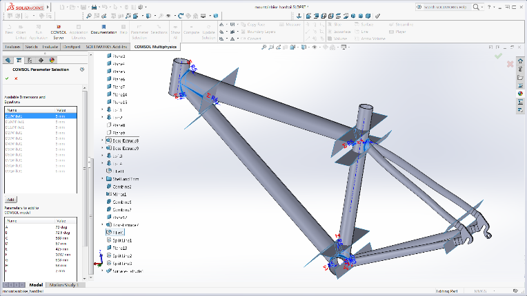
| Geometry Modeling and Interfacing with CAD Software | The core COMSOL Multiphysics® package provides geometry modeling tools for creating parts using solid objects, surfaces, curves, and Boolean operations. Geometries are defined by sequences of operations,
where each operation is able to receive input parameters for easy edits and parametric studies in multiphysics models. The connection between the geometry definition and defined physics settings is fully
associative — a change in the geometry will automatically propagate related changes throughout the associated model settings.
Geometric entities such as material domains and surfaces can be grouped into selections for subsequent use in physics definitions, meshing, and plotting. Additionally, a sequence of operations can be used to create a parametric geometry part, including its selections, which can then be stored in a Part Library for reuse in multiple models. The import of all standard CAD and ECAD files into COMSOL Multiphysics® is supported by the CAD Import Module and ECAD Import Module, respectively. The Design Module further extends the available geometry operations in COMSOL Multiphysics®. Both the CAD Import Module and the Design Module provide the ability to repair and defeature geometries. Surface mesh models, such as in the STL format, can also be imported and then converted to a geometry object by the COMSOL Multiphysics® core package. Import operations are like any other operation in the geometry sequence and can be used with selections and associativity for performing parametric and optimization studies. As an alternative to the defeature and repair capabilities of the COMSOL® software, so-called virtual operations are also supported to eliminate the impact of artifacts on the mesh, such as sliver and small faces, which do not add to the accuracy of the simulation. In converse to defeaturing, virtual operations do not change the curvature or fidelity of the geometry, while yielding a cleaner mesh. |
   |
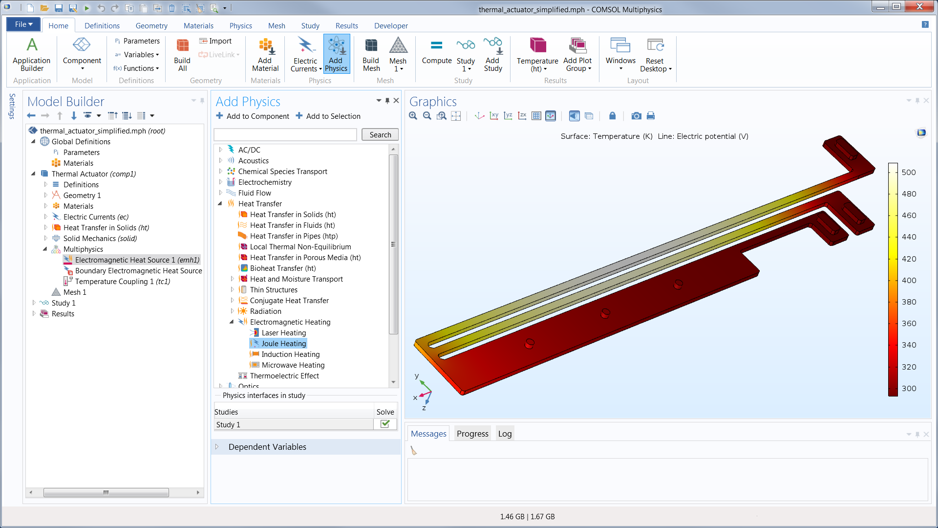
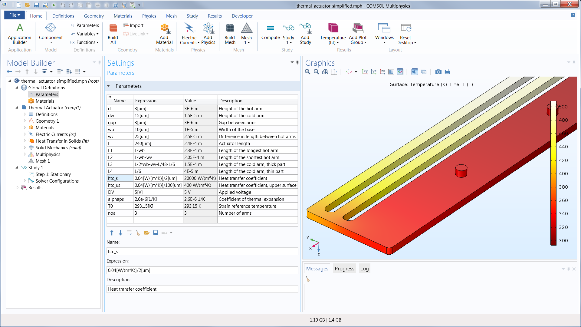
| Predefined Interfaces and Features for Physics-Based Modeling | The COMSOL® software contains predefined physics interfaces for modeling a wide range of physics phenomena, including many common multiphysics couplings. The physics interfaces are dedicated user
interfaces for a particular scientific or engineering field, where all aspects for modeling the phenomena in question are made available for manipulation — from defining the model parameters to discretization
to analyzing the results of the solution.
Upon selecting a particular physics interface, the software suggests available study types, such as time-dependent or stationary solvers. The software also automatically recommends the appropriate numerical discretization of the mathematical model, solver sequence, and visualization and postprocessing settings that are specific to the physics phenomena. The physics interfaces can also be combined freely in order to describe processes that involve multiple physics phenomena. The COMSOL Multiphysics® platform is preloaded with a large set of core physics interfaces for fields such as solid mechanics, acoustics, fluid flow, heat transfer, chemical species transport, and electromagnetics. By expanding the core package with add-on modules from the COMSOL® product suite, you unlock a range of more specialized user interfaces that expand modeling capabilities within specific engineering fields. |
 |
| Transparency and Flexibility via Equation-Based Modeling | To really be useful for scientific and engineering studies and innovation, a software has to allow for more than just a hardwired environment. It should be possible to provide and customize your own model definitions based on mathematical equations directly in the user interface. The COMSOL Multiphysics® software offers this level of flexibility with its built-in equation interpreter that can interpret expressions, equations, and other mathematical descriptions on the fly before it generates the numerical model. Adding and customizing expressions in the physics interfaces allows for freely coupling them with each other to simulate multiphysics phenomena. The capabilities for customization go even further. With the Physics Builder, you can also use your own equations to create new physics interfaces for easy access and manipulation when you want to include them in future models or share them with colleagues. | 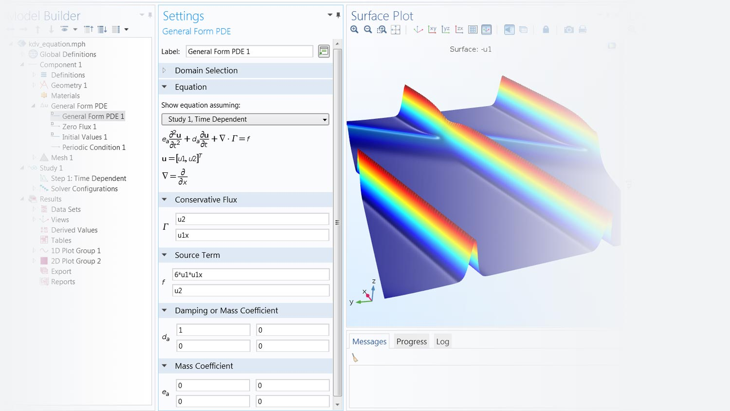 |
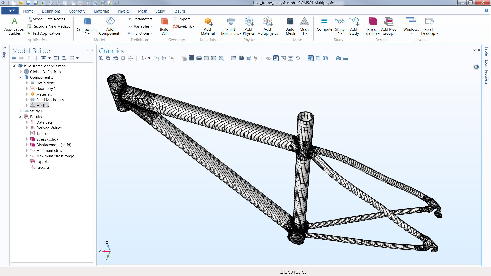
| Automated and Manual Meshing | For discretizing and meshing your model, the COMSOL Multiphysics® software uses different numerical techniques depending on the type of physics, or the combination of physics, that you are studying. The predominant discretization methods are finite-element based (for a complete list of methods, see the solvers section of this page). Accordingly, the general-purpose meshing algorithm creates a mesh with appropriate element types to match the associated numerical methods. For example, the default algorithm may use free tetrahedral meshing or a combination of tetrahedral and boundary-layer meshing, with a combination of element types, in order to provide faster and more accurate results. For all of the mesh types, mesh refinement, remeshing, or adaptive meshing can be performed during the solution process or study step sequence. | 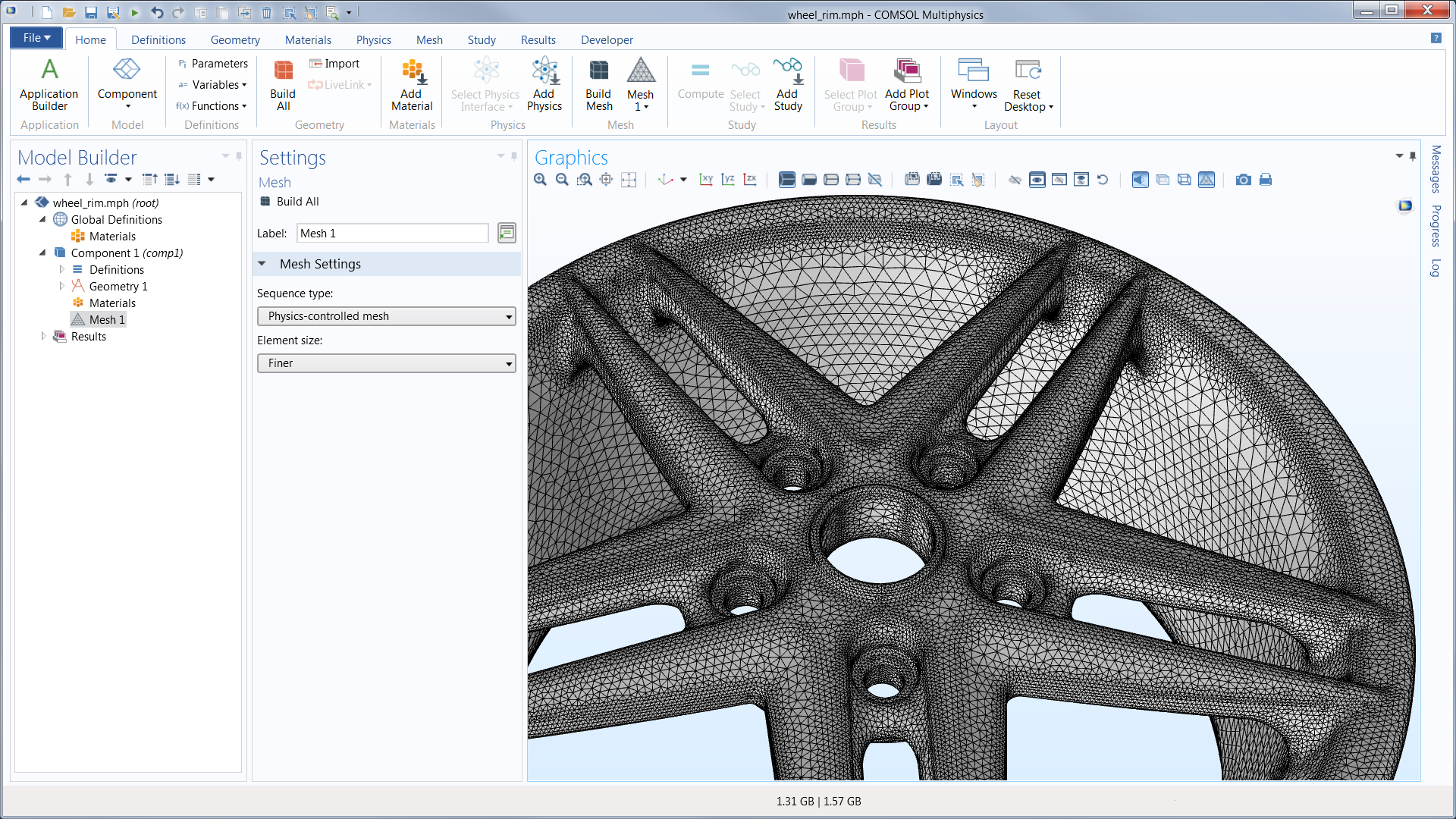 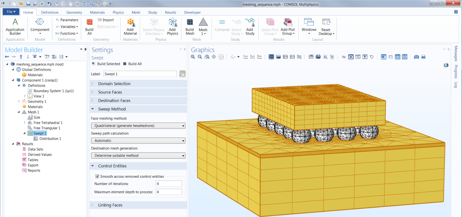 |
| Study Step Sequences, Parameter Studies, and Optimization | When you select a physics interface, a number of different studies (analysis types) are suggested by COMSOL Multiphysics®. For example, for solid mechanics analyses,
the software suggests time-dependent, stationary, or eigenfrequency studies; for CFD problems, the software would only suggest time-dependent and stationary studies. Other study
types can also be freely selected for any analysis that you perform. Study step sequences structure the solution process to allow you to select the model variables for which you
want to solve in each study step. The solution from any of the previous study steps can be used as input to a subsequent study step.
Any study step can be run with a parametric sweep, which can include one or multiple parameters in a model, from geometry parameters to settings in the physics definitions. Sweeps can also be performed using different materials and their defined properties, as well as over lists of defined functions. Optimization studies, using the Optimization Module, can be performed for topology optimization, shape optimization, or parameter estimations based on a multiphysics model. COMSOL Multiphysics® offers both gradient-free and gradient-based methods for optimization. For parameter estimation, least-squares formulations and general optimization problem formulations are available. Built-in sensitivity studies are also available, where they compute the sensitivity of an objective function with respect to any parameter in the model. |
 |
| State-of-the-Art Numerical Methods for Accurate Solutions | The equation interpreter in the COMSOL Multiphysics® software delivers the best possible fuel to the numerical engine: the fully coupled system of PDEs for stationary (steady), time-dependent,
frequency-domain, and eigenfrequency studies. The system of PDEs is discretized using the finite element method (FEM) for the space variables (x, y, z). For some types of problems, the boundary element
method (BEM) can also be used to discretize space. For space- and time-dependent problems, the method of lines is used, where space is discretized with FEM (or BEM), thus forming a system of ordinary
differential equations (ODEs). These ODEs are then solved using advanced methods, including implicit and explicit methods for time stepping. Time-dependent and stationary (steady) problems can be nonlinear,
also forming nonlinear equation systems after discretization. The engine in COMSOL Multiphysics® delivers the fully coupled Jacobian matrix, which is the compass that points the nonlinear solver to the solution.
A damped Newton method is used for solving the nonlinear system for stationary problems or during time stepping for time-dependent problems. The Newton method then solves a sequence of linear equation systems,
using the Jacobian matrix, in order to find the solution to the nonlinear system. For linear problems (also solved in the steps of the nonlinear solver, see above),
the COMSOL® software provides direct and iterative solvers. The direct solvers can be used for small- and midrange-sized problems, while the iterative solvers can be used
for larger linear systems. The COMSOL® software provides a number of iterative solvers with cutting-edge preconditioners, such as multigrid preconditioners. These preconditioners
provide robustness and speed in the iterative solution process.
The different physics interfaces can also provide the solver settings with suggestions on the best possible default settings for a family of problems. These settings are not hardwired; you can change and manually configure the solver settings directly under each solver node in the user interface to tune the performance for your specific problem. When available, the solvers and other computationally intense algorithms are fully parallelized to make use of multicore and cluster computing. Both shared and distributed memory methods are available for direct and iterative solvers as well as for large parametric sweeps. All steps of the solution process can make use of parallel computing. |
 |
| Extended Visualization and Postprocessing Tools for Publication-Ready Modeling Results | Show off your results to the world. COMSOL Multiphysics® sports powerful visualization and postprocessing tools so that you can present your results in a meaningful and polished manner. You can use the built-in tools or expand your visualizations with derived physical quantities by entering mathematical expressions into the software. Therefore, you can visualize just about any quantity of interest related to your simulation results in COMSOL Multiphysics®. Visualization capabilities include surface, slice, isosurface, cut plane, arrow, and streamline plots, to name just a few plot types. A range of numerical postprocessing tools are available for evaluation of expressions, such as integrals and derivatives. You can compute the max, min, average, and integrated values of any quantity or derived quantities throughout volumes, on surfaces, along curved edges, and at points. Postprocessing tools specific to certain areas of engineering and science have also been included in many of the physics-based modules. | 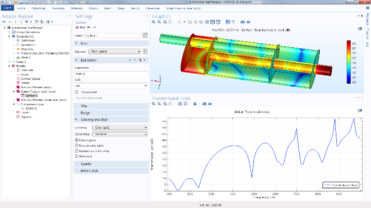 |
Proprietary software by: IntelliSuite
| Name | Description | Instruments/Softwares |
|---|---|---|
| Introduction | IntelliSuite is a tightly integrated design environment that will link your entire MEMS organization together. Built to scale from a point tool to an organization-wide tool, IntelliSuite unifies various engineering and manufacturing tasks into a single living design environment. Designed around collaboration, IntelliSuite allows the design, process, packaging and system teams collaborate on MEMS devices that can be prototyped and manufactured with fewer costly iterations. |  |
| Management | As an engineering manager, IntelliSense provides you all the tools you need to monitor every aspect of the MEMS development. You can explore MEMS development at different granularity from high-level cost estimates and yield projections to mid-level design analysis studies, low-level process flow or metrology data. Intended for use company-wide, IntelliSuite supplies an effective mechanism to consolidate your broad organizational MEMS knowledge in one repository. |  |
| Device | With IntelliSuite, we furnish device designers like you with the comprehensive design exploration tools necessary to follow your unlimited creativity. Thats why IntelliSuite includes SYNPLE and a full suite of FEM/BEM analysis tools that will allow you to design such diverse MEMS as sensors and actuators, RF and optical MEMS, and microfluidic devices and biosystems. | 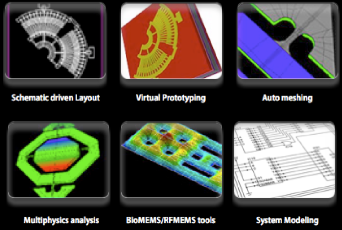 |
| Process flow | If you are a process/manufacturing engineer, our design for manufacturing (DFM) tools grant you the capability to implement your first-time right designs. The across-the-board selection of IntelliSense process tools include virtual prototyping and 3D traveler visualization, thin film material characterization and optimization tools and databases, wet and dry-etch simulators, and Monte Carlo tools for yield prediction. So, whatever your process engineering goals maybe, our process-specific tools will help you achieve them. | 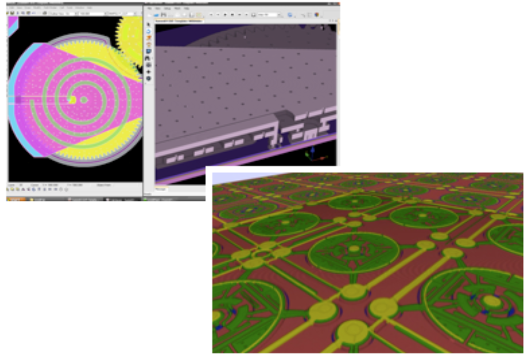 |
| System | IntelliSense enables electrical and system engineers to create and simulate complex MEMS models with exceptional ease. Thanks to SYNPLE, MEMS system design is as fundamental as dragging and dropping, and wiring the schematic. In addition, EDA Linker automatically generates high fidelity HDL (Verilog, VHDL, Simulink or SPICE) models of the MEMS and package to fit your favorite Mixed Signal simulator from Cadence, Mentor, Synopsys, Mathworks or Tanner. Hows that for simple system design? | 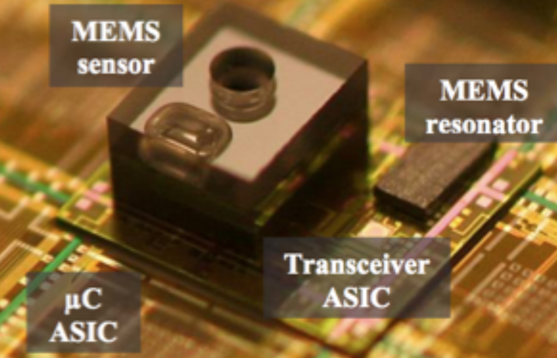 |
| Packaging | As a packaging engineer, IntelliSense offers you tools for thermal, mechanical and high-frequency modeling of your devices. Parametric scripting capabilities allow you to effortlessly create a range of packages, such as SOICs, DIPs, QFPs etc. Whats more, wafer-level encapsulation and related stress analyses may be performed with ease. As a result, you can wrap up your projects quickly and efficiently! | 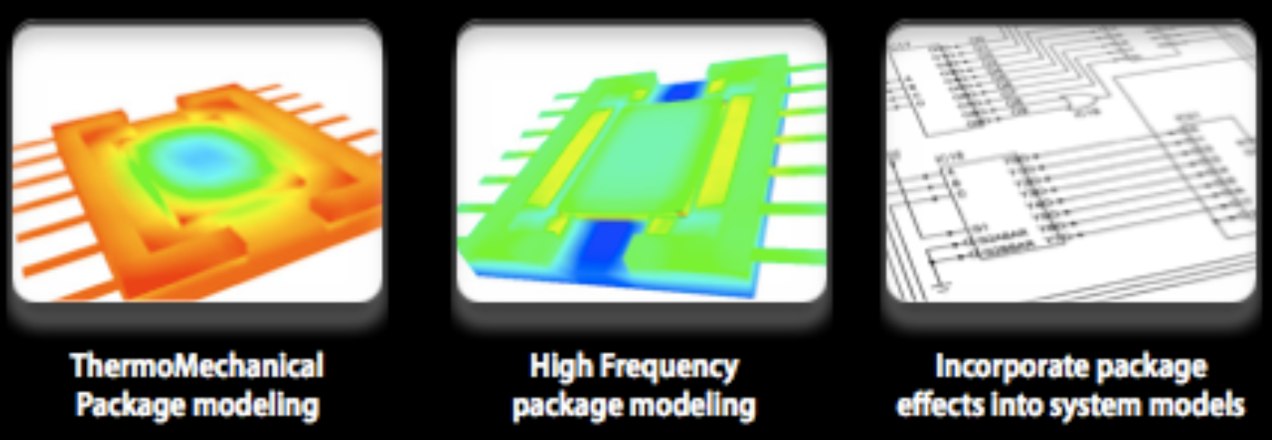 |
| Test | Working together, IntelliSuite and SYNPLE give test engineers a straightforward method for creating parametric test structures and design of experiments (DoE) during the layout process. Whats more, our analysis and system simulation tools allow you to perform a vast subset of MIL-STD (750/883), JEDEC (JESD22) and Telcordia (Belcore) tests in software before the actual fabrication. For success in your next test, turn to IntelliSuite! | 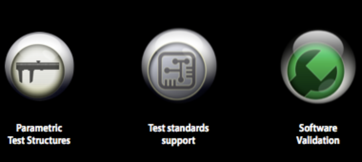 |