
Power Electronics Laboratory
Laboratory Incharge - Dr. Dipu Sarkar
| Name | Description | Instruments/Softwares |
|---|---|---|
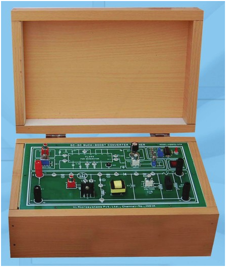
| DC-DC BUCK-BOOST CONVERTER TRAINER | Objectives
|
 |
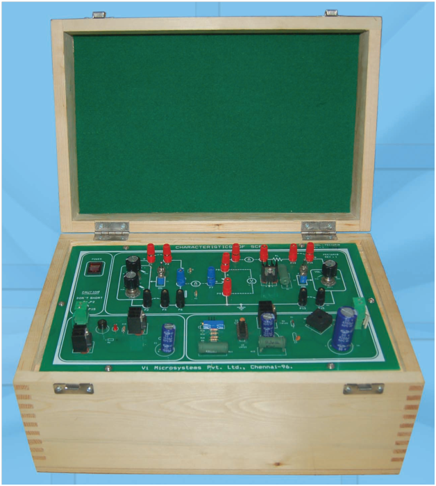
| DYNAMIC CHARACTERISTICS OF SCR & MOSFET | A power electronic system consists of one or more power electronic converters. A power electronic converter is made up of some power semiconductor devices controlled by integrated circuits. The switching characteristics of power semiconductor devices permit a power electronic converter to shape the input power of one form to output power of some other form. The dynamic or switching characteristics of devices are always taken into consideration for economical and reliable design of converter equipment. During turn-on and turn-off process, a device is subjected to different voltages across it and different currents through it. The time variations of the voltage and current during turn-ON and turn-OFF process give the dynamic or switching characteristics of a device. | 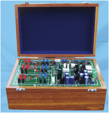 |
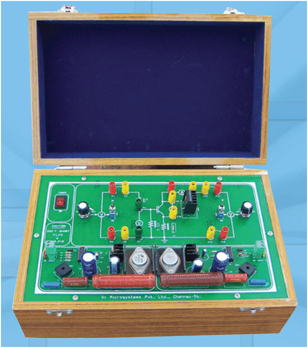
| IGBT & MOSFET CHARACTERISTICS STUDY TRAINER | Objectives
|
 |
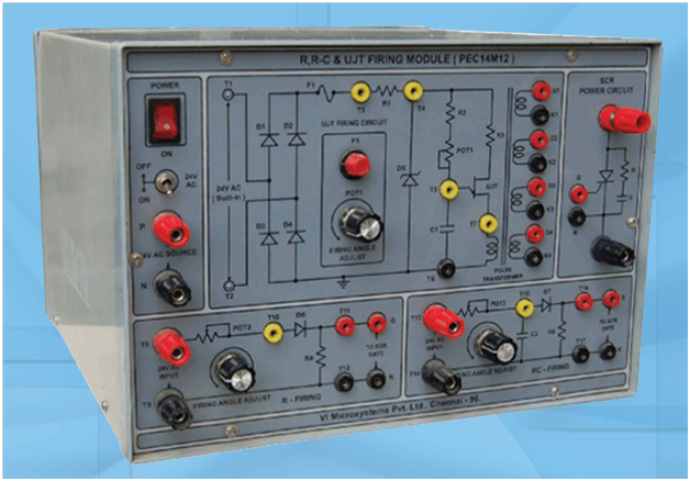
| R, RC & UJT FIRING MODULE | Power electronics deals with the application of solid-state electronics for the control and conversion of electric power. Conversion techniques require the switching ON/OFF of power semi conductor devices.
Modern Power Electronics started with the invention of SCR commonly known as thyristor in 1956. At present, a number of power switching semiconductor devices are available namely BJT, MOSFET, IGBT and GTO etc. All these devices are turned ON/OFF through control terminal, either base or gate as the case may be. This makes simple power circuit. |
 |
| SCR DC CHOPPER MODULE | A Thyristor is turned ON by applying the signal to its gate cathode circuit. For the purpose of power control or power conditioning, a conducting thyristor must be turned OFF as desired. As stated before, the turn off a thyristor means bringing the device from forward conduction state to forward blocking state. The thyristor turn off requires that (i) Its Anode current falls below the holding current. (ii) A reverse voltage is applied to thyristor for a sufficient time to enable it to recover to blocking state. Commutation is defined as the process of turning of the thyristor. Once thyristor starts conducting, gate loses control over the device, therefore, external means are to be applied to commutate the thyristor. Several commutation techniques have been developed with the sole objective of reducing their turn-off (or commutation) time. | 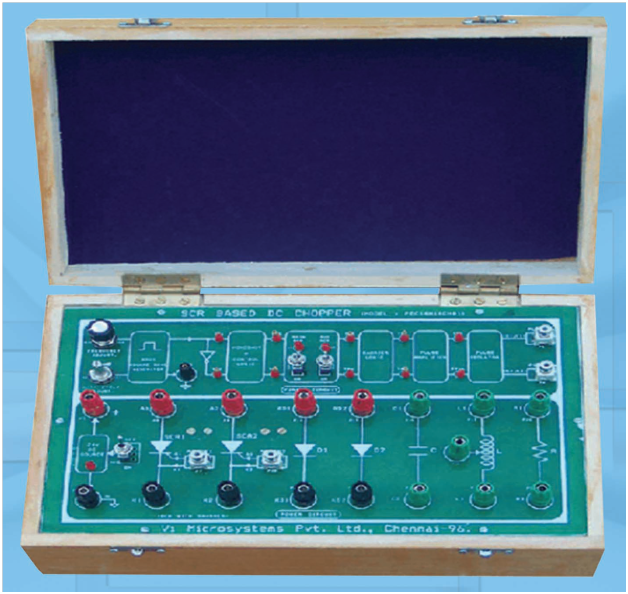 |
| SINGLE PHASE AC VOLTAGE CONTROLLER | The Single Phase AC Voltage Controller using SCRs/TRIAC are used to obtain controlled AC voltages from the fixed AC mains input voltage. The output voltage is varied by controlling the firing angle of the SCRs/TRIAC. The AC Voltage controllers are simple & less expensive. The efficiency of these controllers is generally above 90%. The SCRs/TRIAC in phase controlled circuits are turned “ON” by a gate trigger signal (α), generated in synchronism with the AC mains voltage. SCRs/TRIAC are turned “OFF” due to natural (or) line Commutation. Since these controllers convert from AC to AC Voltage, it is called AC-AC converters and is used extensively in industrial applications. | 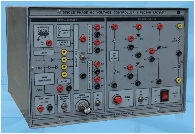 |
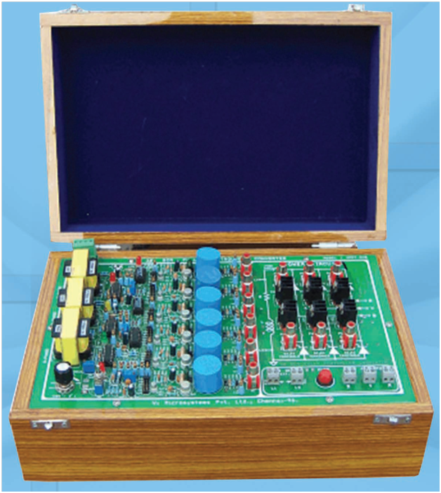
| SINGLE PHASE SCR FULLY CONTROLLED CONVERTER | The current electronics technology is mostly applied to industrial application. Especially, the control of DC and AC motor in factory industrial applications. The power electronics consist of
electronics control circuit and the power circuit. The power electronics device is an assembly of control circuit and power circuit to drive static and dynamic load. Objective
|
 |
| SINGLE PHASE SCR HALF CONTROLLED CONVERTER |
Objective
|
 |
| 3-Φ SCR FULLY CONTROLLED CONVERTER | Objective
|
 |
| VI CHARACTERISTICS OF SCR | Objective
|
 |
| VI CHARACTERISTICS OF TRIAC | Objective
|
|